Sunday, June 28, 2009

The cathode ray tube (CRT) is a vacuum tube containing an electron gun (a source of electrons) and a fluorescent screen, with internal or external means to accelerate and deflect the electron beam, used to create images in the form of light emitted from the fluorescent screen. The image may represent electrical waveforms (oscilloscope), pictures (television, computer monitor), radar targets and others.
Color CRTs have three separate electron guns (shadow mask) or electron guns that share some electrodes for all three beams (Sony Trinitron, and licensed versions)
The CRT uses an evacuated glass envelope which is large, deep, heavy, and relatively fragile. Display technologies without these disadvantages, such as flat plasma screens, liquid crystal displays, DLP, OLED displays have replaced CRTs in many applications and are becoming increasingly common as costs decline.
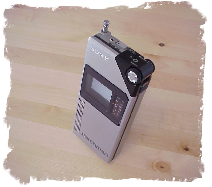
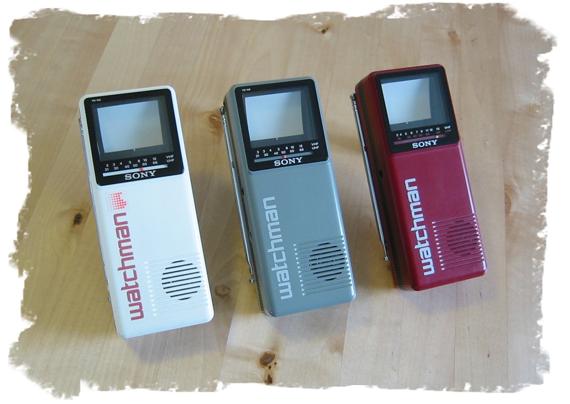
An exception to the typical bowl-shaped CRT would be the flat CRTs used by Sony in their Watchman series (the FD-210 was introduced in 1982). One of the last flat-CRT models was the FD-120A. The CRT in these units was flat with the electron gun located roughly at right angles below the display surface thus requiring sophisticated electronics to create an undistorted picture free from effects such as keystoning.

General description
The earliest version of the CRT was invented by the German physicist Ferdinand Braun in 1897 and is also known as the 'Braun tube'. It was a cold-cathode diode, a modification of the Crookes tube with a phosphor-coated screen. The first version to use a hot cathode was developed by John B. Johnson (who gave his name to the term Johnson noise) and Harry Weiner Weinhart of Western Electric, and became a commercial product in 1922.
The cathode rays are now known to be a beam of electrons emitted from a heated cathode inside a vacuum tube and accelerated by a potential difference between this cathode and an anode. The screen is covered with a crystalline phosphorescent coating (doped with transition metals or rare earth elements), which emits visible light when excited by high-energy electrons. The beam (or beams, in color CRTs) is deflected either by a magnetic or an electric field to move the bright dot(s) to the required position on the screen. External electromagnets deflect the beams magnetically, while internal plates placed near to and alongside the beam deflect it electrostatically. (Electrostatic deflection is used only for single-beam tubes.)
In television sets and computer monitors the entire front area of the tube is scanned repetitively and systematically in a fixed pattern called a raster. A raster is a rectangular array of closely-spaced parallel lines, scanned one at a time, from left to right (and, ever so slightly, "downhill", because the beam is moving steadily down while drawing the image frame). An image is produced by modulating the intensity of each of the three electron beams, one for each primary color (red, green, and blue) with a received video signal (or another signal derived from it). In all CRT TV receivers except some very early models (The earliest commercial TV receivers used electrostatic deflection, even by the end of the 1940s, many of them relying on the famous 7JP4), the beam is deflected by magnetic deflection, a varying magnetic field generated by coils (the deflection yoke), driven by electronic circuits, around the neck of the tube.


CRT details

Oscilloscope CRTs
For use of an oscilloscope, the design is somewhat different from that in a TV or monitor. Rather than tracing out a raster, the electron beam is directly steered along an arbitrary path, while its intensity is kept constant. So electrostatic deflection is used. Usually the beam is deflected horizontally (X) by a varying potential difference between a pair of plates (inside the neck, of course, part of the electron gun) to its left and right, and vertically (Y) by plates (also inside, part of the gun) above and below, although magnetic deflection is possible (but never seen in modern oscilloscopes). The instantaneous position of the beam will depend upon the X and Y voltages. The first commercial CRT, the WE224, was an electrostatic deflection tube, with a soft vacuum, made by Western Electric intended to be used in the first oscilloscopes.

Color CRTs
Color tubes use three different phosphors which emit red, green, and blue light respectively. They are packed together in stripes (as in aperture grille designs) or clusters called "triads" (as in shadow mask CRTs). Color CRTs have three electron guns, one for each primary color, arranged either in a straight line or in a triangular configuration (the guns are usually constructed as a single unit). Each gun's beam reaches the dots of exactly one color; a grille or mask absorbs those electrons that would otherwise hit the wrong phosphor. Since each beam starts at a slightly different location within the tube, and all three beams are perturbed in essentially the same way, a particular deflection charge will cause the beams to hit a slightly different location on the screen (called a 'sub pixel'). Color CRTs with the guns arranged in a triangular configuration are known as delta-gun CRTs, because the triangular formation resembles the triangular shape of the Greek letter Δ (delta). While having deep color reproduction, CRTs can often exaggerate red.

Convergence in color CRTs
The three beams in color CRTs would not, by themselves, strike the screen at the same place at the same time. Uncorrected, the three colors in a typical image would be unacceptably misaligned. Elaborate measures are needed to make the beams converge properly over the entire screen. For one, static convergence brings the beams together, while dynamic convergence (such as from auxiliary coils near the deflection yoke) maintains convergence over the whole screen.
Delta-gun CRTs required the electronically driven convergence coils placed on a "triangle" device on the deflection yoke, powered from the deflection oscillators through a complex set of tunable coils, capacitors and resistors. This type had around 15 points of manual adjustment to align the color and was usually located on a board from the side of the TV case, which could be accessed without dismounting the rear cover of the TV, and easily accessed while viewing a test grid picture on the screen.
Flat-gun modern CRTs require no power for the convergence magnets.


Beam-landing trim magnets
Modern shadow-mask color CRTs have a set of six weak ring magnets around their necks, behind the deflection yoke. These magnets have tabs that permit them to be rotated around the neck to correct beam-landing errors that would affect color purity and cannot be corrected otherwise. (Each of the three beams must excite only the color of phosphor it is intended to; this is color purity.)
In the magnet sets, each ring of one pair has N and S poles diametrically opposite, creating a dipolar field. Rotating these together orients the field, while relative rotation between the pair causes the individual ring fields to aid, to have no effect on, or cancel each other, depending upon relative position.
Similarly, a second pair has four poles, alternating N and S around each ring. This pair provides a quadrupolar field, and its magnitude and orientation are adjusted as with the dipole-field magnets.
Finally, the third pair has six poles, again N and S alternating around the ring, and provides a hexapolar field.
When adjusted, the field inside the neck is a composite of the three types of field, and ensures that each beam lands only on the color of phosphor that it is intended to excite.

Fast events
When displaying one-shot fast events the electron beam must deflect very quickly, with few electrons impinging on the screen, leading to a faint or invisible display. A simple improvement can be attained by fitting a hood on the screen against which the observer presses his face, excluding extraneous light, but oscilloscope CRTs designed for very fast signals give a brighter display by passing the electron beam through a micro-channel plate just before it reaches the screen. Through the phenomenon of secondary emission this plate multiplies the number of electrons reaching the phosphor screen, giving a brighter display, possibly with a slightly larger spot.

Phosphor persistence
The phosphors used in the screens of oscilloscope tubes are different from those used in the screens of other display tubes. Phosphors used for displaying moving pictures should produce an image which fades rapidly to avoid smearing of new information by the remains of the previous picture; i.e., they should have relatively-short persistence. An oscilloscope will often display a trace which repeats unchanged, so longer persistence is not a problem; but it is a definite advantage when viewing a single-shot event, so longer-persistence phosphors are used.
There were moving-film oscilloscope cameras in which film movement provided the time base; they functioned much like strip-chart recorders.

Phosphor colors and designations
An oscilloscope trace can be any color without loss of information, so a phosphor with maximum effective luminosity is usually used. The eye is most sensitive to green: for visual and general-purpose use the P31 phosphor gives a visually bright trace, and also photographs well and is reasonably resistant to burning by the electron beam. Earlier, the green P1 phosphor was used for the same purposes, but it burned more easily and had a somewhat shorter persistence. For displays meant to be photographed rather than viewed, the blue trace of the P11 phosphor gives higher photographic brightness; it has a very short persistence. For extremely slow displays, such as radar PPIs, very-long-persistence phosphors such as P7, which produce a blue trace followed by a longer-lasting amber or yellow afterimage, are used. P7 is a dual-layer phosphor, and the long-persistence layer is excited by the light from the blue phosphor rather than from the electron beam. Color TV CRT phosphors are collectively designated P22

Graticules
The phosphor screen of most oscilloscope tubes contains a permanently-marked internal graticule, a simple array of squares that serves as a reference grid. It divides the screen using Cartesian coordinates. This internal graticule allows for the easy measurement of signals with no worries about parallax error. Less expensive oscilloscope tubes may instead have an external graticule of glass or acrylic plastic. Most graticules can be side-illuminated for use in a darkened room. The markings disperse the light, appearing bright, while the smooth surface acts like a light pipe.

Implosion protection

Oscilloscope tubes almost never contain integrated implosion protection (see below). External implosion protection must always be provided, either in the form of an external graticule or, for tubes with an internal graticule, a plain sheet of glass or plastic. The implosion protection shield is often colored to match the light emitted by the phosphor screen; this improves the contrast as seen by the user.

Monday, June 22, 2009

In computing, a printer is a peripheral which produces a hard copy (permanent human-readable text and/or graphics) of documents stored in electronic form, usually on physical print media such as paper or transparencies. Many printers are primarily used as local peripherals, and are attached by a printer cable or, in most newer printers, a USB cable to a computer which serves as a document source. Some printers, commonly known as network printers, have built-in network interfaces (typically wireless or Ethernet), and can serve as a hardcopy device for any user on the network. Individual printers are often designed to support both local and network connected users at the same time.

In addition, a few modern printers can directly interface to electronic media such as memory sticks or memory cards, or to image capture devices such as digital cameras, scanners; some printers are combined with a scanners and/or fax machines in a single unit, and can function as photocopiers. Printers that include non-printing features are sometimes called Multifunction Printers (MFP), Multi-Function Devices (MFD), or All-In-One (AIO) printers. Most MFPs include printing, scanning, and copying among their features. A Virtual printer is a piece of computer software whose user interface and API resemble that of a printer driver, but which is not connected with a physical computer printer.

Printers are designed for low-volume, short-turnaround print jobs; requiring virtually no setup time to achieve a hard copy of a given document. However, printers are generally slow devices (30 pages per minute is considered fast; and many inexpensive consumer printers are far slower than that), and the cost per page is actually relatively high. The printing press remains the machine of choice for high-volume, professional publishing. However, as printers have improved in quality and performance, many jobs which used to be done by professional print shops are now done by users on local printers; see desktop publishing. The world's first computer printer was a 19th century mechanically driven apparatus invented by Charles Babbage for his Difference Engine.

Printing technology


Printers are routinely classified by the underlying print technology they employ; numerous such technologies have been developed over the years. The choice of print engine has a substantial effect on what jobs a printer is suitable for, as different technologies are capable of different levels of image/text quality, print speed, low cost, noise; in addition, some technologies are inappropriate for certain types of physical media (such as carbon paper or transparencies).
Another aspect of printer technology that is often forgotten is resistance to alteration: liquid ink such as from an inkjet head or fabric ribbon becomes absorbed by the paper fibers, so documents printed with a liquid ink sublimation printer are more difficult to alter than documents printed with toner or solid inks, which do not penetrate below the paper surface.
Checks should either be printed with liquid ink or on special "check paper with toner anchorage".[2] For similar reasons carbon film ribbons for IBM Selectric typewriters bore labels warning against using them to type negotiable instruments such as checks. The machine-readable lower portion of a check, however, must be printed using MICR toner or ink. Banks and other clearing houses employ automation equipment that relies on the magnetic flux from these specially printed characters to function properly.

Obsolete and special-purpose printing technologies
The following technologies are either obsolete, or limited to special applications though most were, at one time, in widespread use.
Impact printers rely on a forcible impact to transfer ink to the media, similar to the action of a typewriter. All but the dot matrix printer rely on the use of formed characters, letterforms that represent each of the characters that the printer was capable of printing. In addition, most of these printers were limited to monochrome printing in a single typeface at one time, although bolding and underlining of text could be done by overstriking, that is, printing two or more impressions in the same character position. Impact printers varieties include, Typewriter-derived printers, Teletypewriter-derived printers, Daisy wheel printers, Dot matrix printers and Line printers. Dot matrix printers remain in common use in businesses where multi-part forms are printed, such as car rental service counters. An overview of impact printing contains a detailed description of many of the technologies used.
Pen-based plotters were an alternate printing technology once common in engineering and architectural firms. Pen-based plotters rely on contact with the paper (but not impact, per se), and special purpose pens that are mechanically run over the paper to create text and images.

Monday, June 15, 2009

In electronics, an integrated circuit (also known as IC, microcircuit, microchip, silicon chip, or chip) is a miniaturized electronic circuit (consisting mainly of semiconductor devices, as well as passive components) that has been manufactured in the surface of a thin substrate of semiconductor material. Integrated circuits are used in almost all electronic equipment in use today and have revolutionized the world of electronics.
A hybrid integrated circuit is a miniaturized electronic circuit constructed of individual semiconductor devices, as well as passive components, bonded to a substrate or circuit board.

Introduction

Integrated circuits were made possible by experimental discoveries which showed that semiconductor devices could perform the functions of vacuum tubes, and by mid-20th-century technology advancements in semiconductor device fabrication. The integration of large numbers of tiny transistors into a small chip was an enormous improvement over the manual assembly of circuits using discrete electronic components. The integrated circuit's mass production capability, reliability, and building-block approach to circuit design ensured the rapid adoption of standardized ICs in place of designs using discrete transistors.


Invention

The integrated circuit was conceived by a radar scientist, Geoffrey W.A. Dummer (1909-2002), working for the Royal Radar Establishment of the British Ministry of Defence, and published at the Symposium on Progress in Quality Electronic Components in Washington, D.C. on May 7, 1952. He gave many symposia publicly to propagate his ideas.
Dummer unsuccessfully attempted to build such a circuit in 1956.
The integrated circuit can be credited as being invented by both Jack Kilby of Texas Instruments and Robert Noyce of Fairchild Semiconductor working independently of each other. Kilby recorded his initial ideas concerning the integrated circuit in July 1958 and successfully demonstrated the first working integrated circuit on September 12, 1958. Kilby won the 2000 Nobel Prize in Physics for his part of the invention of the integrated circuit. Robert Noyce also came up with his own idea of integrated circuit, half a year later than Kilby. Noyce's chip had solved many practical problems that the microchip developed by Kilby had not. Noyce's chip, made at Fairchild, was made of silicon, whereas Kilby's chip was made of germanium.
Early developments of the integrated circuit go back to 1949, when the German engineer Werner Jacobi (Siemens AG) filed a patent for an integrated-circuit-like semiconductor amplifying device showing five transistors on a common substrate arranged in a 2-stage amplifier arrangement. Jacobi discloses small and cheap hearing aids as typical industrial applications of his patent. A commercial use of his patent has not been reported.
A precursor idea to the IC was to create small ceramic squares (wafers), each one containing a single miniaturized component. Components could then be integrated and wired into a bidimensional or tridimensional compact grid. This idea, which looked very promising in 1957, was proposed to the US Army by Jack Kilby, and led to the short-lived Micromodule Program (similar to 1951's Project Tinkertoy). However, as the project was gaining momentum, Kilby came up with a new, revolutionary design: the IC.
The aforementioned Noyce credited Kurt Lehovec of Sprague Electric for the principle of p-n junction isolation caused by the action of a biased p-n junction (the diode) as a key concept behind the IC.
There are two main advantages of ICs over discrete circuits: cost and performance. Cost is low because the chips, with all their components, are printed as a unit by photolithography and not constructed one transistor at a time. Furthermore, much less material is used to construct a circuit as a packaged IC die than as a discrete circuit. Performance is high since the components switch quickly and consume little power (compared to their discrete counterparts), because the components are small and close together. As of 2006, chip areas range from a few square mm to around 350 mm², with up to 1 million transistors per mm².


Generations

SSI, MSI and LSI
The first integrated circuits contained only a few transistors. Called "Small-Scale Integration" (SSI), digital circuits containing transistors numbering in the tens provided a few logic gates for example, while early linear ICs such as the Plessey SL201 or the Philips TAA320 had as few as two transistors.
SSI circuits were crucial to early aerospace projects, and vice-versa. Both the Minuteman missile and Apollo program needed lightweight digital computers for their inertial guidance systems; the Apollo guidance computer led and motivated the integrated-circuit technology[citation needed], while the Minuteman missile forced it into mass-production.
These programs purchased almost all of the available integrated circuits from 1960 through 1963, and almost alone provided the demand that funded the production improvements to get the production costs from $1000/circuit (in 1960 dollars) to merely $25/circuit (in 1963 dollars).[citation needed] They began to appear in consumer products at the turn of the decade, a typical application being FM inter-carrier sound processing in television receivers.
The next step in the development of integrated circuits, taken in the late 1960s, introduced devices which contained hundreds of transistors on each chip, called "Medium-Scale Integration" (MSI).
They were attractive economically because while they cost little more to produce than SSI devices, they allowed more complex systems to be produced using smaller circuit boards, less assembly work (because of fewer separate components), and a number of other advantages.
Further development, driven by the same economic factors, led to "Large-Scale Integration" (LSI) in the mid 1970s, with tens of thousands of transistors per chip.
Integrated circuits such as 1K-bit RAMs, calculator chips, and the first microprocessors, that began to be manufactured in moderate quantities in the early 1970s, had under 4000 transistors. True LSI circuits, approaching 10000 transistors, began to be produced around 1974, for computer main memories and second-generation microprocessors.

VLSI

The final step in the development process, starting in the 1980s and continuing through the present, was "very large-scale integration" (VLSI). The development started with hundreds of thousands of transistors in the early 1980s, and continues beyond several billion transistors as of 2007.
There was no single breakthrough that allowed this increase in complexity, though many factors helped. Manufacturing moved to smaller rules and cleaner fabs, allowing them to produce chips with more transistors with adequate yield, as summarized by the International Technology Roadmap for Semiconductors (ITRS). Design tools improved enough to make it practical to finish these designs in a reasonable time. The more energy efficient CMOS replaced NMOS and PMOS, avoiding a prohibitive increase in power consumption. Better texts such as the landmark textbook by Mead and Conway helped schools educate more designers, among other factors.
In 1986 the first one megabit RAM chips were introduced, which contained more than one million transistors. Microprocessor chips passed the million transistor mark in 1989 and the billion transistor mark in 2005. The trend continues largely unabated, with chips introduced in 2007 containing tens of billions of memory transistors.

ULSI, WSI, SOC and 3D-IC


To reflect further growth of the complexity, the term ULSI that stands for "Ultra-Large Scale Integration" was proposed for chips of complexity of more than 1 million transistors.
Wafer-scale integration (WSI) is a system of building very-large integrated circuits that uses an entire silicon wafer to produce a single "super-chip". Through a combination of large size and reduced packaging, WSI could lead to dramatically reduced costs for some systems, notably massively parallel supercomputers. The name is taken from the term Very-Large-Scale Integration, the current state of the art when WSI was being developed.
System-on-a-Chip (SoC or SOC) is an integrated circuit in which all the components needed for a computer or other system are included on a single chip. The design of such a device can be complex and costly, and building disparate components on a single piece of silicon may compromise the efficiency of some elements. However, these drawbacks are offset by lower manufacturing and assembly costs and by a greatly reduced power budget: because signals among the components are kept on-die, much less power is required (see Packaging, above).
Three Dimensional Integrated Circuit (3D-IC) has two or more layers of active electronic components that are integrated both vertically and horizontally into a single circuit. Communication between layers uses on-die signaling, so power consumption is much lower than in equivalent separate circuits. Judicious use of short vertical wires can substantially reduce overall wire length for faster operation.

Wednesday, June 10, 2009

An uninterruptible power supply (UPS), also known as a battery back-up, provides emergency power and, depending on the topology, line regulation as well to connected equipment by supplying power from a separate source when utility power is not available. It differs from an auxiliary or emergency power system or standby generator, which does not provide instant protection from a momentary power interruption. A UPS, however, can be used to provide uninterrupted power to equipment, typically for 5–15 minutes until an auxiliary power supply can be turned on, utility power restored, or equipment safely shut down.
While not limited to safeguarding any particular type of equipment, a UPS is typically used to protect computers, data centers, telecommunication equipment or other electrical equipment where an unexpected power disruption could cause injuries, fatalities, serious business disruption or data loss. UPS units come in sizes ranging from units which will back up a single computer without monitor (around 200 VA) to units which will power entire data centers or buildings (several megawatts).

Common power problems
There are various common power problems that UPS units are used to correct:
1) Power failure
2) Voltage sag
3) Voltage spike
4)Under-voltage (brownout)
5)Over-voltage
6) Line noise
7)Frequency variation
8) Switching transient
9) Harmonic distortion
UPS units are divided into categories based on which of the above problems they address, and some manufacturers categorize their products in accordance with the number of power related problems they address.

Technologies
The general categories of modern UPS systems are on-line, line-interactive, and standby. An on-line UPS uses a "double conversion" method of accepting AC input, rectifying to DC for passing through the battery (or battery strings), then inverting back to AC for powering the protected equipment. A line-interactive UPS maintains the inverter in line and redirects the battery's DC current path from the normal charging mode to supplying current when power is lost. In a standby ("off-line") system the load is powered directly by the input power and the backup power circuitry is only invoked when the utility power fails. Most UPS below 1 kVA are of the line-interactive or standby variety which are usually less expensive.
For large power units, Dynamic Uninterruptible Power Supply are sometimes used. A synchronous motor/alternator is connected on the mains via a choke. Energy is stored in a flywheel. When the mains power fails, an Eddy-current regulation maintains the power on the load. DUPS are sometimes combined or integrated with a diesel-generator[clarification needed], forming a diesel rotary uninterruptible power supply, or DRUPS.
A Fuel cell UPS have been developed in recent years using hydrogen and a fuel cell as a power source, potentially providing long run times in a small space.


Offline / standby

The Offline / Standby UPS (SPS) offers only the most basic features, providing surge protection and battery backup. Usually the Standby UPS offers no battery capacity monitoring or self-test capability, making it the least reliable type of UPS since it could fail at any moment without warning. These are also the least expensive, selling for as little as US$40. The SPS may be worse than using nothing at all, because it gives the user a false sense of security of being assured protection that may not work when needed the most.
With this type of UPS, a user's equipment is normally connected directly to incoming utility power with the same voltage transient clamping devices used in a common surge protected plug strip connected across the power line. When the incoming utility voltage falls below a predetermined level the SPS turns on its internal DC-AC inverter circuitry, which is powered from an internal storage battery. The SPS then mechanically switches the connected equipment on to its DC-AC inverter output. The switchover time is stated by most manufacturers as being less than 4 milliseconds, but typically can be as long as 25 milliseconds depending on the amount of time it takes the Standby UPS to detect the lost utility voltage.[citation needed]


Hybrid Topology / Double Conversion on Demand
Recently there have been hybrid topology UPSs hitting the marketplace. These hybrid designs do not have an official designation, although one name used by HP and Eaton is Double Conversion on Demand.This style of UPS is targeted towards high efficiency applications while still maintaining the features and protection level offered by double conversion.
A hybrid (double conversion on demand) UPS operates as an offline/standby UPS when power conditions are within a certain preset window. This allows the UPS to achieve very high efficiency ratings. When the power conditions fluctuate outside of the predefined windows, the UPS switches to online/double conversion operation.In double conversion mode the UPS can adjust for voltage variations without having to use battery power, can filter out line noise and control frequency. Examples of this hybrid/double conversion on demand UPS design are the HP R8000, HP R12000, HP RP12000/3 and the Eaton BladeUPS.


Typically, the high-mass flywheel is used in conjunction with a motor-generator system. These units can be configured as:
A motor driving a mechanically connected generator,
A combined synchronous motor and generator wound in alternating slots of a single rotor and stator,
A Hybrid Rotary UPS, designed similar to an Online UPS, except that it uses the flywheel in place of batteries. The rectifier drives a motor to spin the flywheel, while a generator uses the flywheel to power the inverter.
In case #3 the motor generator can be synchronous/synchronous or induction/synchronous. The motor side of the unit in case #2 and #3 can be driven directly by an AC power source (typically when in inverter bypass), a 6-step double-conversion motor drive, or a 6 pulse inverter. Case #1 uses an integrated flywheel as a short-term energy source instead of batteries to allow time for external, electrically coupled gensets to start and be brought online. Case #2 and #3 can use batteries or a free-standing electrically coupled flywheel as the short-term energy source.

Capacitors
UPSs can be equipped with maintenance-free capacitors to extend service life .

Applications

N+1
In large business environments where reliability is of great importance, a single huge UPS can also be a single point of failure that can disrupt many other systems. To provide greater reliability, multiple smaller UPS modules and batteries can be integrated together to provide redundant power protection equivalent to one very large UPS. "N+1" means that If the load can be supplied by N modules, the installation will contain N+1 modules. In this way, failure of one module will not impact system operation

Multiple redundancy
Many computer servers offer the option of redundant power supplies, so that in the event of one power supply failing, one or more other power supplies are able to power the load. This is a critical point - each power supply must be able to power the entire server by itself.
Redundancy is further enhanced by plugging each power supply into a circuit (i.e. to a different circuit breaker).
While it is common practice by uninformed people to plug each of these individual power supplies into one single UPS, redundant protection can be extended further yet by connecting each power supply to its own UPS. This provides double protection from both a power supply failure and a UPS failure, so that continued operation is assured. This configuration is also referred to as 2N redundancy. If the budget does not allow for two identical UPS units then it is common practice to plug one power supply into mains power and the other into the UPS.

Outdoor use
When a UPS system is placed outdoors, it should have some specific features that guarantee that it can tolerate weather with a 'minimal to none' effect on performance. Factors such as temperature, humidity, rain, and snow among others should be considered by the manufacturer when designing an outdoor UPS system. Operating temperature ranges for outdoor UPS systems could be around −40 °C to +55 °C.
Outdoor UPS systems can be pole, ground (pedestal), or host mounted. Outdoor environment could mean extreme cold, in which case the outdoor UPS system should include a battery heater mat, or extreme heat, in which case the outdoor UPS system should include a fan system or an air conditioning system.

Internal systems
UPS systems can be designed to be placed inside a computer chassis. There are two types of Internal UPS. The first type is a miniaturized regular UPS that is made small enough to fit into a 5.25″ CD-ROM slot bay of a regular computer chassis. The other type are re-engineered switching power supplies that utilize dual power sources of AC and/or DC as power inputs and have an AC/DC built-in switching management control units.
All these connections are connected to a common point called 'Earth'.

Difficulties faced with generator use
The voltage and frequency of the power produced by a generator depends on the engine speed. The speed is controlled by a system called a governor. Some governors are mechanical, some are electronic. The job of the governor is to keep the voltage and frequency constant, while the load on the generator changes. This may pose a problem where, for example, the startup surge of an elevator can cause short "blips" in the frequency of the generator or the output voltage, thus effecting all other devices powered by the generator. Many transmission sites will have backup diesel generators - in the case of AM, the load presented by the transmitters changes in line with the signal level. This leads to the scenario where the generator is constantly trying to correct the output voltage and frequency as the load changes.

Friday, June 5, 2009

Nonvolatile BIOS memory refers to a small memory on PC motherboards that is used to store BIOS settings. It was traditionally called CMOS RAM because it used a low-power CMOS SRAM (such as the Motorola MC146818 or similar) powered by a small battery when system power was off. The term remains in wide use but it has grown into a misnomer: nonvolatile storage in contemporary computers is often in EEPROM or flash memory (like the BIOS code itself); the remaining usage for the battery is then to keep the real-time clock going. The NVRAM has a typical capacity of 512 bytes, which is enough for all BIOS-settings.

CMOS mismatch
CMOS mismatch errors typically occur if the computer's power-on self-test program:
Finds a device that is not recorded in the CMOS.
Does not find a device that is recorded in the CMOS.
Finds a device that has different settings than those recorded for it in CMOS.
Detects a CMOS checksum error.


CMOS battery

The memory and real-time clock are generally powered by a CR2032 lithium coin cell. These cells last two to ten years, depending on the type of motherboard, ambient temperature and the time that the system is powered off, while other common cell types can last significantly longer or shorter periods, such as the CR2016 which will generally last about 40% as long. Higher temperatures and longer power-off time will shorten cell life. When replacing the cell, the system time and CMOS BIOS settings may revert to default values. This may be avoided by replacing the cell with the power supply master switch on. On ATX motherboards, this will supply 5V standby power to the motherboard even if it is apparently "switched off", and keep the CMOS memory energised.


Resetting the CMOS settings
To access the BIOS setup when the machine fails to operate, occasionally a drastic move is required. In older computers with battery-backed RAM, removal of the battery and short circuiting the battery input terminals for a while did the job; in some more modern machines this move only resets the RTC. Some motherboards offer a CMOS-reset jumper or a reset button. In yet other cases, the EEPROM chip has to be desoldered and the data in it manually edited using a programmer. Sometimes it is enough to ground the CLK or DTA line of the I²C bus of the EEPROM at the right moment during boot, this requires some precise soldering on SMD parts. If the machine lets you boot but does not want to let you into the BIOS setup, one possible recovery is to deliberately "damage" the CMOS checksum by doing direct port writes using debug.exe, corrupting some bytes of the checksum-protected area of the CMOS RAM; at the next boot, the computer typically resets its setting to factory defaults.